Oven

Oven
Oven.We have delivered several hundred ovens both in Japan and internationally since its development in 1960
Yamato Sanko, Mfg., Co., Ltd. developed an oven for metal printing and painting in 1960. Since its launch, we have delivered several hundred ovens both in Japan and internationally.
Based on this extensive experience, we aim to progress even further by continuing to take on the challenge of developing easy-to-use ovens that pass the highest quality standards required by the metal printing market.

Features

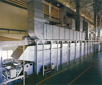
Providing energy-saving, antipollution and environmental countermeasures, the direct combustion deodorizing/indirect heat recovery oven incorporates a waste heat recovery system and exhaust processing system based on a fume incinerator. The oven fully satisfies the various conditions for ink and paint that are required in the coating process to form an attractive and strong coated surface.

1. Direct combustion deodorizer: fume incinerator Complete combustion of volatile solvents for perfect deodorization

The exhaust gas from the oven contains a large amount of volatile solvents. This gas is fed to the fume incinerator (direct combustion deodorizer) for combustion and deodorization.
This exhaust gas passes through a secondary heat exchanger (waste heat recovery) and is heated in advance to a high temperature of 300°C or higher before being sent into the fume incinerator.
This ensures the complete combustion of resin compounds that are normally difficult to burn in the fume incinerator. The volatile solvents in the exhaust gas are also utilized as a heat source.

2. Primary heat exchanger: Clean hot air that contains no combustion gas

The hot air sent inside the oven consists of the hot combustion gas after deodorization and air from outside that have passed through the primary heat exchanger and been heated indirectly.
Therefore, the hot air sent inside the oven does not contain NOx (nitrogen oxide).
The humidity and oxygen concentration in the oven is kept to the same condition as the outside air. This produces a high-quality coating with excellent hardness and gloss.

3. Double ducts in exhaust air path: Effective energy saving and prevention of fume adherence

The temperature of the exhaust gas from the oven is normally about 100°C to 120°C.
The exhaust gas also contains a large amount of volatile gas.
A double duct structure is used where the exhaust duct of the oven passes inside the combustion gas duct after deodorization, for the dual objectives of preventing fume adherence and recovering waste heat after deodorization.

4. Secondary heat exchanger: Indirect heat recovery for an exhaust gas flow that saves energy

The temperature of the exhaust gas that passes through the double ducts is about 200°C. When a direct combustion deodorization method is used, a large amount of fuel is required because deodorizing is performed at a high temperature of about 800°C.
For this reason, a secondary heat exchanger is used to recover waste heat after deodorization and raise the exhaust gas temperature, thus reducing fuel consumption.
The exhaust gas is heated here to 300°C or higher before being sent to the fume incinerator in an energy-saving flow.

Airflow/Internal structure

1. Swirling airflow: Even baking of printed or painted surfaces

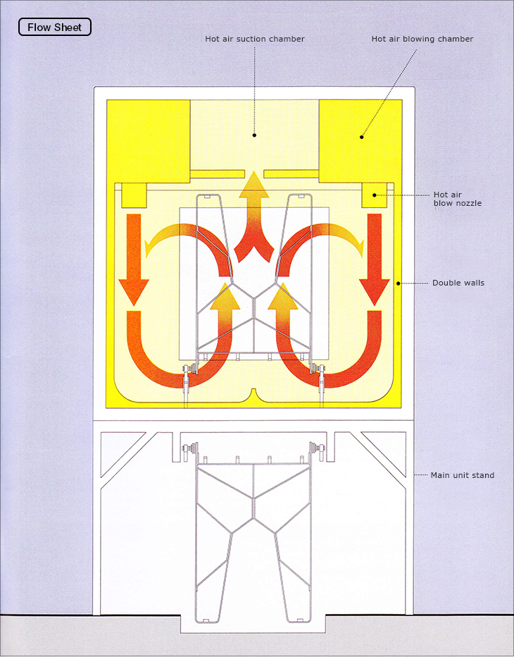
The hot airflow from the hot air blow nozzles on the left and right, the hot airflow between the double walls, and the center suction effect make a swirling airflow form on the left and right inside the furnace.
This airflow creates a fine, turbulent flow between the metal boards to make the contact of the hot air on the board surface even and perform the ideal convection flow heating.
The swirling airflow bakes printed surfaces or painted surfaces evenly with no irregularities to guarantee a high-quality finish.

2. Zone control: For both energy saving and high quality

The hot airflow volume and temperature adjustments required for production conditions such as paint type, metal board material, thickness, dimensions and speed can be performed accurately through the combination of the fume incinerator, hot air blow chamber sensors in each zone, controllers, and automatic dampers.

3. Forced exhaust at inlet and sealed zone: Sealing of heating and cooling zones

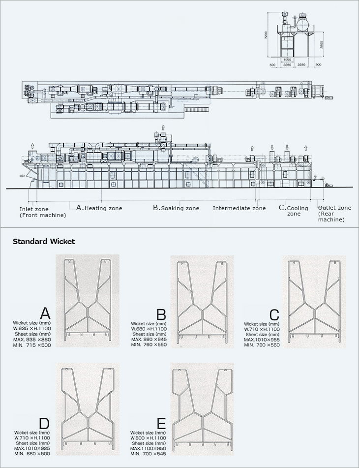
The forced exhaust by the exhaust port at the oven inlet seals the heating zone inlet to prevent odors and hot air from leaking outside. A sealed zone of about 500 mm is provided between the soaking zone and cooling zone for forced exhaust. This prevents mutual interference between the soaking zone and cooling zone, whose temperatures vary greatly.

4. Double walls prevent fume adherence Prevents air blow nozzle fluttering

When the hot air passes between the double walls of the furnace, the wall surface retains a high temperature to prevent fume adherence. In addition, the swirling airflow is straightened.
The flow volume and flow direction of the hot air blow nozzles can be adjusted to prevent the metal boards from flapping. Therefore, fluttering does not occur.

Flow Sheet.Hot air suction chamber.Hot air blowing chamber.Hot air blow nozzle.Double walls.Main unit stand

1. Automatic tension adjuster for chain (abrasion prevention 1)

The air cylinder automatically adjusts the tension of the wicket conveyor chain.

2. Automatic lubricator for chain (abrasion prevention 2)

The automatic lubricator supplies an extremely small amount of oil to lubricate the chain. This prevents all problems related to the chain.

3. Wide chain with a 1-inch pitch (abrasion prevention 3)

The wide chain enables smooth movement of the wicket in the front machine and rear machine.

4. S-45C hardened rail: Prevents contamination by worn particles

The rail is made of S-45C hardened steel for minimal wearing, and the airflow speed inside the furnace is slow, so worn particles are not blown up.

5. Wicket: Design and performance based on our long experience

The wicket is made of steel equivalent to JIS-10C with a nickel-plated finish for antirust performance and easy cleaning of adhered tar.

6. Maintenance space: Easy to inspect and clean inside the furnace

There is maintenance space on both sides of the wicket inside the furnace. This makes inspection and cleaning easy without removing the wicket. It also means less work for operators to ensure that the furnace interior is safe and clean.

7. Unit structure: Short installation time

The main unit frame and side walls have an integrated structure to enable installation in a short time.

Oven Capacity Selection Chart (A + B).Processing time (min.).Machine length (m).The models of MY ovens are described as follows.(Example: MYIH-80GN3).M = METAL
.Y = YAMATO SANKO MFG. CO. LTD..I = I: 1-inch wicket pitch specification / No symbol: 1.25-inch specification.H = H: Painting line (high temperature) / L: Printing line (low temperature).80 = Sheet processing capacity perminute (number of sheets).G = G: Heat source is gas / K: Kerosene / E: Electricity.N = N: New type.3 = Number of control zones for heating and soaking.MY oven product configuration. Standard oven (normal type). Direct. combustion deodorizing/indirect heat recovery oven*. Direct combustion deodorizing/direct heat recovery oven.Catalyst deodorizing/direct heat recovery oven.* The direct combustion deodorizing/indirect heat recovery oven is the latest flagship model of the MY ovens.The direct combustion deodorizing/indirect heat recovery oven is used in these descriptions.

Models/Specifications

Inlet zone(Front machine). A. Heating zone. B. Soaking zone. Intermediate zone. C. Cooling zone Outlet zone(Rear machine)

Printing Oven (Standard).Capacity (sheets/min). A – Heating zone. B – Soaking zone. C – Cooling zone. Zone length (mm). Processing time (min.). Zone length (mm). Processing time (min.). Zone length (mm). Processing time (min.). Zone length (mm). Processing time (min.)

Painting Oven (Standard). Capacity (sheets/min). A – Heating zone. B – Soaking zone. C – Cooling zone. Zone length (mm). Processing time (min.). Zone length (mm)
Processing time (min.). Zone length (mm). Processing time (min.). Zone length (mm). Processing time (min.)

Optional Devices

Wicket Cleaner.This wicket cleaner is constructed of two booths and two tanks for water and alkaline water.The alkaline components are not brought into the furnace, which prevents problems. The device can be operated automatically.
Wicket Preheater.The wicket preheater is extremely effective from both perspectives of quality and saving energy.
It uses as a heat source the excess energy from the heat source of the oven. The device is operated automatically.

Inverter Control.Precise Zone ControlThe hot air circulation fan can be controlled with the inverter. Adjusting the hot airflow volume saves energy and ensures a higher quality finish.Fluttering Prevention.In particular, inverter control of the hot air circulation fan in the heating zone where there is a large flow of hot air fully prevents fluttering.Energy Saving Operation
Energy saving operation is possible by switching the main hot air fan to low speed and turning off the cooling fan during interruptions such as preparation time or rest time.

MY7000 Oven Intelligent Management System
In the oven intelligent management system (MY7000) developed for MY ovens, production conditions can be easily set. The system also has an operating status monitoring function, an error monitoring function and an operating status recording function.Input via a Touch Panel A touch panel is used for setting the production conditions, enabling easy input for anyone by directly touching the monitor screen with a finger.Information such as the baking temperature, metal board materials, dimensions and production speed are displayed in sequence on a color monitor, and these production conditions are entered using a responsive method.Stored production conditions can be set as a batch.Also, in situations such as rest time or emergency stops, the temperature and airflow can be set for energy saving operation.Operating Status Monitoring Function When operation starts, the operating status can be monitored on a color monitor. The oven flow screen displays information such as the temperature in each zone, the open or closed status of each fan, the gas flow volume of the burner, the electricity amount and the production speed.The gas flow screen displays the status of each valve and the ignition on or off status of the burner on a gas flow diagram. Also, the temperature in each zone and the airflow volume data of each fan are displayed on a graph.Error Monitoring Function Conditions in the oven can be monitored for problems in areas such as the temperature, gas pressure, shut-off valve and fans. In addition to the error location and error status, the countermeasure procedure is also displayed on the screen to contain any problems to the minimum level.Operating Status Recording FunctionDisplays the production results. A hard copy can be made of this screen.

  • Contact
  • Catalog